
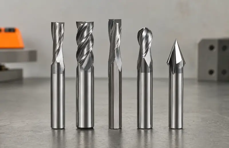
Acrylic can produce a clear, polished-looking routed edge, but it can also soften, smear and weld back to the cutter when heat and chip evacuation are poorly controlled. Choosing the right router bit therefore starts with the exact acrylic grade, operation and machine—not with a universal RPM value.
Quick answer: for many CNC profile cuts in acrylic sheet, a sharp polished solid-carbide O-flute made for plastics is a strong starting category. A single flute leaves generous space for chip evacuation on feed-limited machines. Choose upcut, downcut or straight geometry from workholding, chip flow and visible-face requirements; then use the exact tool manufacturer’s cutting data and test matching scrap.
Which router bit should you use for acrylic?
| Operation | Useful starting category | Why it may help | Critical check |
|---|---|---|---|
| CNC profile through-cut | Polished solid-carbide single O-flute for acrylic/plastics | Large flute space and controlled chip formation | Exact tool approval, workholding and chip evacuation |
| Deep slot or pocket | Plastic-cutting upcut spiral when approved | Moves chips upward from the enclosed cut | Part lift, top-edge finish and available flute space |
| Thin sheet or protected top face | Plastic-cutting downcut or low-helix tool when approved | Can direct force toward the support and protect the top face | Chip packing, heat and spoilboard clearance |
| Handheld template routing | Straight or low-helix plastic-cutting bit approved for hand feeding | More predictable axial force in a controlled jig | The product must explicitly permit handheld use |
| Finishing allowance on an edge | Sharp plastic-finishing tool with light, supported engagement | Removes a planned allowance without repeating the roughing load | Avoid a near-zero pass that only rubs |
| Engraving or V-groove | Plastic-approved engraving cutter for the required included angle | Matches line width and depth | Tip strength, runout, depth and heat in small features |
This table identifies tool families, not a product prescription. Amana Tool, for example, lists both upcut and downcut single-flute acrylic O-flutes, while ACRYLITE guidance notes that one-, two- and three-flute tools may be used. The correct choice depends on the exact cutter, sheet, process and machine.
For the dimensions and limitations to verify before selecting a product, see the neutral single-flute O-flute acrylic tool profile.
Identify the acrylic before choosing the bit
“Acrylic,” PMMA and brand names such as ACRYLITE or Plexiglas describe a material family, not one identical machining condition. Cast and extruded sheet can respond differently to cutting heat, internal stress and finishing. Thickness, surface coating, recycled content and previous thermal history also matter. Read the sheet identification or supplier data instead of guessing from appearance.
Do not treat polycarbonate, PETG, PVC, acetal or solid-surface sheet as acrylic. They are different materials even when a clear panel looks similar. A tool maker may approve one O-flute series for several plastics but publish different starting data for each. PVC also introduces specific health and process concerns; it should not be included merely because a generic “plastic” cutter exists.
Keep the protective film in place only when the sheet manufacturer permits machining with it and the film is firmly bonded. Loose film can wrap around the cutter or hide chip evacuation. Inspect both faces and remove any label, tape or debris that could enter the cut.
O-flute, straight and spiral geometries
Polished O-flute
An O-flute has a large, smooth flute form designed to create and clear a defined chip in compatible plastics. A polished surface reduces places where hot material can adhere. Single-flute versions are common because the open flute provides space for evacuation and allows a useful chip thickness at a lower machine feed than a multi-flute tool running at the same RPM.
“O-flute” is still a family name. Helix, rake, edge polish, diameter, cutting length and intended material vary between part numbers. A tool sold for aluminium is not automatically the preferred acrylic tool even if its profile looks similar. Use the manufacturer’s material list and dimensioned drawing.
Straight and low-helix plastic cutters
A straight or low-helix cutter reduces axial pull compared with a strong spiral and can be useful in supported thin sheet or approved hand-fed operations. It may not evacuate a deep enclosed slot as effectively as an upcut. The correct choice is the one that balances chip flow, holding force and edge finish for the actual cut.
Two or more flutes
Multiple edges can increase productivity and finish on a machine capable of maintaining the required feed. They also reduce flute space and require a higher feed to preserve the same nominal chip load. Do not replace a one-flute tool with a two-flute tool while keeping feed and RPM unchanged: nominal chip thickness would be cut in half.
Upcut, downcut or straight for acrylic?
An upcut can pull chips out of a profile or pocket, which helps limit recutting. Its axial force can also lift a thin or poorly held sheet and may affect the top edge. Verify vacuum hold-down, clamps, tabs and the remaining part area before choosing it.
A downcut directs force and chips downward. It may help keep a thin panel against a spoilboard or protect the upper face, but it can pack hot chips beneath the tool. Provide a compatible exit path and stop if chips accumulate or the kerf begins to smear.
A straight or very low-helix geometry limits axial force but does not remove the need for evacuation. It can suit some handheld jigs or thin-sheet processes when the exact product allows that use. Read the more general upcut, downcut and compression guide, but do not assume that a wood compression bit is suitable for acrylic.
Diameter, cutting length and flute count
Diameter
A small diameter creates tight internal radii and narrow features, but it is less rigid and has less flute volume. A larger diameter can be stiffer and provide more evacuation space, but it requires larger inside radii, wider kerf, compatible power and a suitable speed range. Choose from part geometry and machine capability—not from sheet thickness alone.
Cutting length and projection
Use the shortest cutting length that covers the real engagement. Extra projection increases leverage, deflection and chatter. ACRYLITE’s routing guidance gives product-specific length-to-diameter limits for HSS, brazed carbide and solid carbide tools; treat those figures as guidance for its stated process, not permission to ignore the cutter manufacturer’s limits.
Keep the flute transition outside the collet, grip only clean straight shank and do not bottom the tool inside the collet. The shank size must match exactly. Runout makes one edge carry more load, worsens finish and can turn a nominal chip-load calculation into an unreliable assumption.
Flute count
Flute count belongs in every feed calculation. The basic relationship is:
Feed rate = RPM × number of effective cutting edges × chip load
The result is only a relationship between inputs. The target chip load must come from the exact tool manufacturer for the acrylic type and engagement. See the beginner speeds and feeds guide for the full verification method.
Feed, RPM and chip formation
Acrylic routing must remove heat with the chip. When feed is too low for the selected RPM and flute count, the edge may rub instead of producing a substantial chip. Heat then stays in the cut and softens the polymer. Excessive engagement, a dull edge, recutting and a slowing toolpath can produce the same symptom, so changing RPM alone is not a diagnosis.
Maximum RPM is a ceiling, not a target. Select a working combination inside the tool and machine limits, derived from manufacturer data. Confirm that the machine can actually maintain the calculated feed in corners and short moves. If it cannot, consider an approved single-flute tool, reduced engagement or a simpler path rather than accepting severe rubbing.
Observe chip form. Defined chips that leave the kerf are generally more useful than powder, sticky strands or material welded to the edge. Do not touch a chip or cutter to judge temperature while the setup is active. Stop, isolate power and allow components to cool before inspection.
Use only cooling or lubrication methods approved by the sheet, cutter and machine manufacturers. An improvised liquid can craze acrylic, attack protective film, create a fire or electrical hazard, or turn chips into a paste. Effective vacuum extraction or a controlled chip-clearing method must not compromise guards or expose people to flying particles.
Workholding, entry and toolpath
Support acrylic uniformly on a clean spoilboard or fixture. A small chip trapped under the sheet can scratch it or prevent flat holding. Vacuum tables need enough remaining surface area and sealed leakage paths; clamps must stay outside every tool and rapid-move envelope. Small finished parts may require tabs, onion-skinning or another proven retention method.
Entry matters because dwelling in one location creates heat. Use the cutter manufacturer’s approved plunge, ramp or predrilled entry method. Not every plastic-cutting bit is center cutting. A shallow ramp can reduce localized loading only when tool geometry, CAM path and available space support it.
Avoid unnecessary pauses, repeated spring passes and tiny segmented moves. In corners, the controller may slow the actual feed while RPM remains constant. Choose an internal radius the cutter can follow smoothly and verify the most demanding corner during the scrap test.
Plan the finish. A roughing pass can leave a controlled allowance for a finishing pass, but a nearly zero-width pass may rub. The correct stock allowance and direction of cut depend on the manufacturer, machine, rigidity and edge requirement. Flame polishing or solvent finishing introduces separate fire, stress and health risks and is outside the scope of router-bit selection.
A conservative, traceable test method
- Identify the sheet: record acrylic type, grade, thickness, film and supplier document.
- Select the exact tool: confirm part number, machine type, material approval, diameter, shank, cutting length, flute count and maximum RPM.
- Prepare mechanics: clean the collet, minimize projection, check runout and secure clean matching scrap.
- Start from published data: use the manufacturer’s chip-load or feed range for the stated material and engagement.
- Reduce risk through engagement: use an approved shallow or reduced-width test rather than an arbitrarily slow feed.
- Test the real path: include entry, straight cut, corner and exit—not only an easy line.
- Inspect after isolation: look for defined chips, smearing, whitening, chatter, scratches, edge accuracy and material on the cutter.
- Change one variable: record each adjustment and repeat on the same material.
Use the MatchMyTools selector to narrow the tool family and the CNC calculators for arithmetic. Neither replaces the exact cutting-data sheet or a controlled trial.
Troubleshooting acrylic routing
| Symptom | Likely areas to inspect | First safe response |
|---|---|---|
| Melted or smeared edge | Dull tool, low actual chip load, recutting, deep engagement or corner slowdown | Stop, isolate power, clear the setup and return to exact manufacturer data |
| Plastic welded to the cutter | Heat, poor polish or geometry, trapped chips, damaged edge | Do not continue; remove and inspect only after lockout |
| White, frosted or chipped edge | Vibration, impact, unsuitable geometry, excessive load or sheet stress | Check holding, runout, projection, entry and tool condition |
| Good straights, damaged corners | Actual feed reduction, tight radius, dwell or segmented CAM motion | Review real machine motion and use a compatible radius/path |
| Sheet lifts or shifts | Upcut force, weak vacuum, insufficient clamps, small remaining area | Stop and redesign workholding before changing cutting data |
| Scratched finished face | Chips under the sheet, dragging chips, damaged film or dirty fixture | Clean support and improve chip control before the next test |
Safety
Disconnect and isolate power before touching the cutter, collet or work area. Keep machine guards and interlocks in service, secure the sheet and keep hands outside the cutting path. Use suitable eye and hearing protection and control flying chips. OSHA’s router guidance highlights point-of-operation contact and flying chips; the machine and workplace requirements that apply to you remain authoritative.
Stop for a moving sheet, abnormal vibration, broken or sticky chips, smoke, unusual smell, a loaded cutter or loss of extraction. Never exceed the lowest maximum-speed rating in the complete rotating system. A CNC-only cutter must not be used in a handheld or table-mounted router unless its manufacturer explicitly approves that operation.
Frequently asked questions
What is the best router bit for acrylic?
For many CNC profile cuts, a sharp polished solid-carbide O-flute made for acrylic or compatible plastics is a strong starting category. The final choice depends on sheet type, operation, machine, workholding, direction, diameter and the exact manufacturer’s data.
Is one flute or two flutes better for acrylic?
Neither is universally better. A single flute offers more evacuation space and can maintain chip thickness at a lower feed. Two flutes may improve productivity or finish when the machine can maintain the required feed and the manufacturer approves the setup.
Should I lower RPM when acrylic melts?
Not automatically. Melting can result from low actual chip load, a dull edge, recutting, excessive engagement or corner slowdown. Review feed and RPM together with tool condition, evacuation and the exact cutting data.
Can I use a wood router bit on acrylic?
Only if the exact product manufacturer lists the acrylic grade and intended machine. A bit that cuts wood is not automatically polished, shaped or cleared for thermoplastics.
Why does the acrylic turn white after routing?
Whitening may come from rough fracture, vibration, an unsuitable or damaged edge, excessive load, internal material stress or an aggressive entry. Inspect the complete setup and compare a controlled test with the sheet manufacturer’s guidance.
Technical references
- ACRYLITE — Proper method for routing acrylic sheet: flute-count, cutter-material and tool-projection guidance.
- ACRYLITE — Routing fabrication brief: equipment, processing, formulas and troubleshooting.
- Amana Tool — Acrylic-cutting O-flute router bits: manufacturer examples of single-flute upcut and downcut geometries.
- Amana Tool — Router Bit Technical Information: machine-use, shank and collet guidance.
- LMT Onsrud — Fixturing and Routing of Plastics with CNC: chip load, heat, chip rewelding, entry and workholding.
- OSHA — Handheld routers: guarding, flying chips, work control and eye protection.
Important: this guide explains a selection and verification method. The sheet data, exact cutter specifications, machine manual, guarding requirements and a controlled scrap test take priority.
The stated parameters are starting points. Test progressively on scrap and always respect manufacturer limits.