
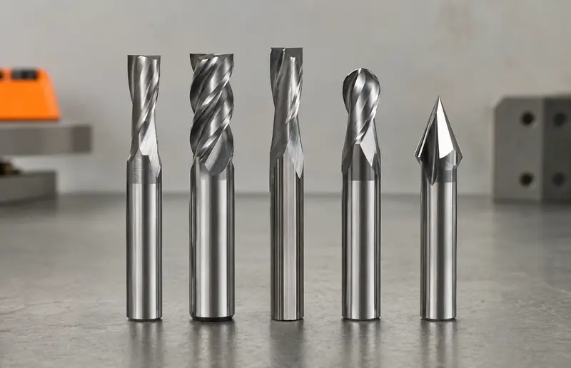
Quick answer: select a metal milling cutter from the operation before choosing diameter, flute count, carbide grade or coating. A square-end mill cuts pockets, slots and shoulders; a ball-nose or corner-radius mill follows 3D profiles; a face mill generates broad flat surfaces; a side-and-face cutter opens or finishes slots; a T-slot or Woodruff cutter makes a defined undercut or keyseat; and a chamfer mill breaks edges or creates an angled feature. Then verify the workpiece material, machine power and rigidity, holder interface, cutting diameter, reach, insert system, maximum speed and manufacturer cutting data.
Types of milling cutters at a glance
| Cutter family | Typical operations | Essential check | Common mistake |
|---|---|---|---|
| Square-end mill | Pockets, slots, contours and shoulders | Center-cutting or permitted entry method | Plunging with a tool not designed for axial entry |
| Ball-nose end mill | 3D surfaces, moulds and finishing | Effective diameter, stepover and contact point | Using nominal diameter for every cutting-speed calculation |
| Corner-radius end mill | Roughing, semi-finishing and radiused floors | Corner radius against the drawing | Choosing a radius too large for the internal feature |
| Roughing end mill | High-volume stock removal where approved | Chipbreaker geometry and finishing allowance | Expecting a finishing surface from a rougher |
| Face mill | Broad flat faces | Entering angle, diameter, inserts and spindle power | Selecting the largest cutter without checking torque |
| Shoulder mill | Faces and nominal 90-degree shoulders | True shoulder capability and axial depth | Assuming every near-90-degree cutter makes a true square wall |
| Side-and-face or slot mill | Slots, grooves and side cuts | Width, arbor, overhang and chip space | Ignoring clearance and chip packing in a deep slot |
| T-slot cutter | T-slots and defined undercuts | Prepared access slot, head and neck dimensions | Trying to remove the complete slot through the narrow neck |
| Woodruff keyseat cutter | Seats for semicircular keys | Key standard, width, diameter and calculated depth | Treating it as interchangeable with a T-slot cutter |
| Chamfer or deburring mill | Chamfers, countersinks and edge breaking | Included angle and engaged diameter | Assuming every common angle matches the drawing |
This table identifies an operation family, not a safe final part number. Similar-looking cutters may have different grades, insert seats, center-cutting capability, permitted ramp angle, maximum speed and workpiece-material range. Use the drawing and exact manufacturer datasheet together.
Dimensions and terms that control compatibility
- Cutting diameter: determines slot width, internal radius and surface speed at a given spindle speed.
- Cutting length or axial depth capability: limits how much of the flute or insert system may engage. It is not automatically equal to the visible flute length.
- Reach and overall length: determine access, but unnecessary length reduces rigidity and can increase deflection and chatter.
- Shank or arbor interface: must match the holder, spindle and retention system. A nominally similar shank is not a substitute for the specified interface.
- Flute or tooth count: changes chip space, feed per revolution and the number of cutting edges in contact.
- Corner radius: strengthens the edge and defines the smallest fillet that the cutter can finish.
- Entering angle: redistributes radial and axial forces in face and shoulder milling. It also changes chip thickness for a given feed.
- Maximum RPM: is an upper limit for the complete rotating assembly, not a recommended cutting speed.
Center-cutting capability and entry strategy
A center-cutting end mill can cut across its center region, but that does not authorize every vertical plunge. Some tools permit ramping, helical interpolation or a limited axial entry angle; others require a predrilled hole or side entry. Indexable bodies can have separate ramping limits. Confirm the exact entry method, ramp angle, axial depth and coolant or chip-evacuation requirement.
Metric, inch and nominal labels
Do not mix a metric tool definition, inch holder and rounded CAM value. The programmed diameter affects cutter compensation and the finished feature. Measure runout and the resulting cut where tolerance requires it, and store the exact part number, unit system, gauge length and corner radius in the tool library.
The principal metal milling-cutter families
1. Square-end mills
Square-end mills are used for pockets, open or closed slots, profiles, floors and shoulders. The end geometry may be sharp, lightly protected or corner-chamfered. A two- or three-flute design generally leaves more chip space than a high-flute-count tool of the same diameter, while more flutes can increase available cutting edges when evacuation and machine conditions allow.
Choose flute count from the material, engagement and evacuation requirement, not from a universal rule. Deep full-width slots need space for chips; a light peripheral finishing pass may use a different design. Cutting length should only be as long as access demands, because a long slender cutter is less rigid.
2. Ball-nose end mills
A ball-nose cutter follows 3D surfaces, dies and moulds. Cutting speed is not uniform across the hemispherical end: it approaches zero at the exact center. Tool inclination, contact point, stepover and surface strategy therefore affect both finish and tool life.
For finishing, a smaller stepover reduces cusp height but increases cycle time. Confirm the CAM system uses the correct ball radius and gauge length. Avoid forcing the tip center through a long cut when a permitted tilted or offset contact strategy would use a more effective part of the edge.
3. Corner-radius or bull-nose end mills
A corner-radius cutter keeps a largely flat end with a defined radius between end and side edges. The radius can strengthen the corner compared with a perfectly sharp square end and is useful in roughing, semi-finishing and radiused pocket floors.
The tool cannot finish an internal fillet smaller than its own geometry. Compare cutter radius with every internal corner and leave a documented finishing allowance if a smaller tool will complete restricted areas later.
4. Roughing end mills
Roughers use serrated or chip-splitting geometry to divide the chip and reduce the length of continuous edge contact in suitable operations. They target material removal, not a final cosmetic wall. Geometry, pitch and workpiece-material rating vary widely.
Leave enough stock for the specified finishing tool and verify that thin walls can tolerate the roughing forces. A rougher does not compensate for weak workholding, excessive overhang or an underpowered spindle.
5. Face mills
Face mills generate broad flat surfaces with inserts arranged around a cutter body. Diameter, insert count, entering angle and pitch must suit spindle power, machine stability, workpiece width and interrupted features. Sandvik describes 45-degree cutters as a common general-purpose face-milling choice because the entering angle balances radial and axial cutting forces, but the exact application still controls selection.
A cutter wider than the workpiece is not automatically ideal. Plan the entry and exit, check insert engagement and avoid striking clamps or unsupported edges. For a finishing pass, insert runout, wiper geometry where applicable and spindle alignment can dominate the resulting surface.
6. Shoulder mills
Shoulder milling generates a face and a peripheral wall at the same time. A true 90-degree requirement is different from roughing with a cutter that only approaches 90 degrees. Check the cutter body’s stated shoulder capability, axial depth, insert geometry and remaining corner radius.
Tool deflection can taper the wall or leave a step between levels. Minimize overhang, use a stable holder and separate roughing from finishing when the tolerance and surface requirement justify it.
7. Side-and-face cutters and slot mills
These disc-like cutters cut on the circumference and side faces to produce slots or side cuts. Sandvik notes that side-and-face milling is often preferred to end milling for groove or slot operations. The best choice still depends on access, machine arrangement, slot width, depth and whether the slot is open or closed.
Verify arbor diameter, keying or drive interface, spacers, direction of mounting and side clearance. Deep slots require an evacuation plan; packed chips can damage the insert, mark both walls and increase load.
8. T-slot cutters
A T-slot cutter machines the undercut after a straight access slot has been prepared. Head diameter and width, neck diameter, reach and insert system must match the drawing. The neck is not intended to remove all the material of a solid full-width slot.
Program adequate entry and exit space, confirm radial engagement and ensure the neck clears the prepared slot. Kennametal’s KTMS line, for example, is a dedicated indexable T-slot system for particular materials and engagement ranges—not a generic substitute for every T-slot dimension.
9. Woodruff keyseat cutters
A Woodruff cutter produces a seat for a standardized semicircular key. It may resemble a small slotting or T-slot cutter, but the design intent and dimensions differ. Select from the applicable key standard, shaft diameter, cutter width and diameter, then calculate and verify the required depth.
A nearly matching cutter can create a seat that is too wide, too deep or poorly positioned. Inspect the mating key and drawing rather than identifying the tool from appearance alone.
10. Chamfer and deburring mills
Chamfer mills break edges, prepare welds and produce angled features or countersinks. The catalog angle may be an included angle or otherwise defined; confirm how it corresponds to the drawing. The effective diameter changes with the axial position and width of the chamfer.
Large engaged widths can chatter even when a small tip looks light. Select the grade, coating and edge preparation for the workpiece, use a rigid projection and avoid treating a general deburring tool as a precision countersink without evidence.
What do “two-size” and “three-size” cutters mean?
Traditional French terminology calls an end-type cutter that cuts on the circumference and one end face a fraise deux tailles. A fraise trois tailles cuts on the circumference and both side faces. English catalogs usually describe the operation or form—end mill, side-and-face cutter or slotting cutter—instead of translating those expressions literally. When purchasing internationally, compare the product drawing and cutting-edge locations rather than the translated name.
HSS, solid carbide and indexable cutters
| Construction | Typical strengths | Principal constraints | Useful checks |
|---|---|---|---|
| High-speed steel (HSS) | Tough, resharpenable and available in special forms | Generally lower useful speed and abrasive wear resistance than carbide | Material grade, heat treatment, edge condition and machine speed range |
| Solid carbide | Rigid, wear resistant and common for small to medium end mills | Less tolerant of impact, poor runout and unstable setups | Shank accuracy, projection, holder cleanliness, microgeometry and coating |
| Indexable carbide | Replaceable edges for face, shoulder and slot milling | Minimum practical diameter, body condition and insert-seat accuracy | Body, insert style, grade, geometry, screw and torque as one system |
| Brazed or special form tool | Dedicated profiles and some repairable constructions | Application-specific limits and specialist servicing | Braze integrity, profile drawing, balance and manufacturer limits |
“Carbide” is not a single performance level. Substrate, grain size, edge preparation, chipbreaker and coating must be selected together for the exact material and operation. Coatings that perform well on steels may not be the right starting point for some aluminium alloys; use the manufacturer’s ISO material group and grade recommendations.
Match the cutter to the machine and holder
- Spindle interface: CAT, BT, HSK, ISO, R8 and other systems are not interchangeable. Retention knob, taper, drive and balancing requirements must all match.
- Holder style: collet chuck, milling chuck, hydraulic holder, shrink-fit, Weldon side-lock holder and shell-mill arbor have different runout, access and torque characteristics.
- Spindle range: small cutters may need high speed; large face mills demand torque. Verify both continuous power and the useful speed range.
- Machine rigidity: spindle bearings, guideways, work envelope and workholding determine the stable engagement available.
- Tool changer limits: mass, diameter, adjacent-pocket clearance and gauge length can restrict an otherwise compatible cutter.
- Coolant and chip control: flood, through-tool coolant, air or minimum-quantity systems are process decisions governed by tool, material, machine and workplace requirements.
Keep the taper, holder bore, collet, shank, insert pockets and screws clean. Minimize projection without creating a collision. Haas emphasizes following the operator’s manual and using the specified tooling for the spindle; a machine’s maximum spindle speed does not authorize an unbalanced or unsuitable tool assembly.
Choose geometry for the workpiece material
| Workpiece group | Starting priority | Chip or heat concern | Selection warning |
|---|---|---|---|
| Aluminium and non-ferrous alloys | Sharp, polished geometry and generous chip space where specified | Built-up edge and chip welding | Not every aluminium alloy or silicon content uses the same grade |
| Carbon and alloy steels | Balanced toughness, wear resistance and stable engagement | Heat and crater or flank wear | Hardness and heat treatment can move the part into a different application range |
| Stainless steel | Sharp positive geometry, consistent feed and controlled heat | Work hardening, long chips and edge chipping | Do not dwell or simply reduce feed without checking chip thickness |
| Cast iron | Grade and geometry matched to graphite structure and hardness | Abrasive dust or short chips | Coolant strategy and enclosure requirements vary by process |
| Heat-resistant superalloys | Rigid setup, application-specific grade and limited engagement | Concentrated heat and rapid notch wear | Use specialist manufacturer data, not generic steel values |
| Hardened materials | Verified hardness range, stable machine and dedicated geometry | Edge chipping and high thermal/mechanical load | Confirm whether milling is approved at the measured hardness |
Material labels are not enough. Record alloy or grade, hardness, condition, scale, interrupted features and required finish. For stainless finishing after machining, the separate stainless-steel grinding-disc guide explains abrasive compatibility. For holes rather than milled cavities, begin with the drill-bit-by-material guide.
A practical milling-cutter selection workflow
- Read the drawing: identify faces, shoulders, slots, pockets, undercuts, radii, tolerance and surface-finish requirements.
- Separate operations: choose roughing, semi-finishing and finishing tools where one cutter cannot meet all priorities efficiently.
- Identify the workpiece: exact alloy or grade, hardness, condition, skin or scale, and interrupted regions.
- Check the machine: spindle interface, speed, torque, power, rigidity, travel, coolant, enclosure and tool-change limits.
- Select the cutter family: end, ball-nose, corner-radius, face, shoulder, slot, T-slot, Woodruff or chamfer.
- Choose construction: HSS, solid carbide or indexable based on diameter, stability, volume, required form and cost per usable edge.
- Verify dimensions: diameter, cutting length, radius, head and neck, arbor or shank, reach and gauge length.
- Build the complete assembly: holder, collet or arbor, retention components, insert, screw and coolant delivery.
- Use exact manufacturer data: cutting speed, feed per tooth, axial depth, radial engagement, ramping and coolant guidance.
- Simulate and prove out: check collisions and remaining stock, then run a controlled first part while monitoring load, sound, chips, temperature and dimensions.
- Inspect and record: document wear pattern, offsets, part result and tool life before changing multiple variables.
The MatchMyTools selector can organize currently supported tool families, but it does not yet calculate a complete metal-milling process. CAM verification, machine limits and the exact cutter manufacturer’s data remain mandatory.
Diagnose the symptom before changing cutters
- Chatter or repeating waves: check projection, holder runout, workholding, spindle condition and tooth engagement. A smaller radial engagement or different cutter pitch may help only after the unstable mechanical condition is identified.
- Oversize slot: measure runout, deflection and actual tool diameter; verify compensation and whether climb/conventional passes deflect in opposite directions.
- Tapered shoulder: reduce unsupported length, confirm finishing allowance and inspect holder or spindle runout. A true 90-degree cutter cannot correct a flexible setup by itself.
- Built-up edge: verify that grade, coating or polish suits the alloy, then check cutting speed, feed, lubrication and chip recutting.
- Rapid corner chipping: inspect entry and exit, interrupted cuts, corner radius, toolpath and workpiece hardness. Do not automatically reduce feed until minimum chip thickness and rubbing risk are considered.
- Poor face-mill finish: inspect insert seating and runout, spindle alignment, cutter position across the work and damaged wiper or finishing edges.
- Blue or recut chips: improve the approved evacuation or coolant method and check flute capacity, slot depth and toolpath. Never remove chips by hand near a rotating tool.
- Unexpected short life: change one controlled variable at a time and photograph or record the wear location. Edge wear, notch wear, fracture and thermal damage do not have the same remedy.
Safety checks before metal milling
- Only trained and authorized personnel should operate the machine; read its manual, warnings and shop procedures first.
- Use the prescribed power-isolation or lockout process before entering a hazardous area, servicing the spindle or handling a cutter.
- Inspect holder, retention system, cutter body, insert seats, screws, collet and shank. Replace damaged or incompatible parts.
- Clamp the workpiece and verify that vise, jaws, fixtures, clamps, table and spindle cannot collide over the complete toolpath.
- Respect the lowest maximum-speed limit among cutter body, inserts, arbor, holder and spindle. Balance rotating assemblies where specified.
- Keep doors, guards, interlocks and chip-control systems in service. OSHA requires guarding against hazards including rotating parts, the point of operation and flying chips.
- Use an approved method for coolant and chip handling; metalworking fluids can present health risks and require workplace controls.
- Simulate, single-block or use another machine-approved prove-out method after a significant setup change. Stop for abnormal vibration, load, sound, heat, smoke or tool movement.
Frequently asked questions
What is the most versatile milling cutter for metal?
A square-end mill is versatile for pockets, slots, contours and shoulders, but it is not universally best. A face mill is usually more suitable for broad faces, a ball-nose for 3D surfaces and dedicated cutters for T-slots or keyseats. The drawing, material, machine, holder and manufacturer’s application data determine the practical choice.
Can an end mill be used for face milling?
Yes, an end mill can face a small area when its geometry and entry are suitable, especially on a smaller machine. A dedicated face mill may be more productive and better supported for a broad surface. Compare spindle power, cutter diameter, entering angle, insert runout, workpiece width and the required finish.
What is the difference between a ball-nose and a corner-radius end mill?
A ball-nose has a hemispherical end and is commonly used for 3D contours; its effective cutting speed falls toward the center. A corner-radius end mill retains a mostly flat bottom with a defined radius joining the side, making it useful for roughing, floors and radiused corners. The drawing decides which profile is correct.
Are T-slot and Woodruff cutters interchangeable?
No. A T-slot cutter creates a T-shaped undercut after an access slot, while a Woodruff cutter produces a seat for a standardized semicircular key. Head, neck, width, diameter, depth calculation and toolpath differ. Select the cutter from the exact feature standard and drawing.
Is carbide always better than HSS for milling?
No. Solid or indexable carbide often supports higher productivity and wear resistance in a rigid setup, but HSS remains useful for some lower-speed machines, special forms, interrupted conditions and short runs. Toughness, speed range, rigidity, diameter, material and regrinding economics must be evaluated together.
Technical sources
- Sandvik Coromant — Milling fundamentals and machine selection
- Sandvik Coromant — Face-milling methods
- Sandvik Coromant — Shoulder milling
- Sandvik Coromant — Groove and slot milling
- Kennametal — Indexable T-slot cutter system
- Haas Automation — Mill operator safety
- OSHA — General machine-guarding requirements
The stated parameters are starting points. Test progressively on scrap and always respect manufacturer limits.