
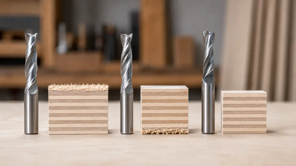
Spiral direction changes more than chip travel. It also changes which face of a panel is supported by the cutting force, how easily heat can leave the slot, and whether a deep cut can be cleared without recutting packed chips. The right choice therefore starts with the operation and the visible face, not with the bit name alone.
Quick answer: choose an upcut when chip evacuation and a clean bottom edge matter most; choose a downcut when the top face must stay clean and the cut is shallow enough to clear chips safely; choose a compression bit for through-cuts in double-sided panels when its upcut-to-downcut transition will sit correctly inside the material.
Upcut vs downcut vs compression: quick comparison
| Geometry | Typical chip direction | Face it usually protects | Common uses | Main limitation |
|---|---|---|---|---|
| Upcut | Up and out of the cut | Bottom face | Deep slots, pockets, mortises, efficient roughing | Can lift fibres or veneer at the top edge |
| Downcut | Down into the cut | Top face | Shallow dadoes, grooves, lettering and top-surface work | Can pack chips and create heat in a deep closed slot |
| Compression | Toward the centre from both faces | Top and bottom faces | Through-cut profiles in veneered or laminated panels | Only works as intended when the transition is inside the material |
These are selection tendencies, not guarantees. Edge quality also depends on sharpness, runout, material support, toolpath, chip load and the manufacturer’s intended application.
What spiral direction actually changes
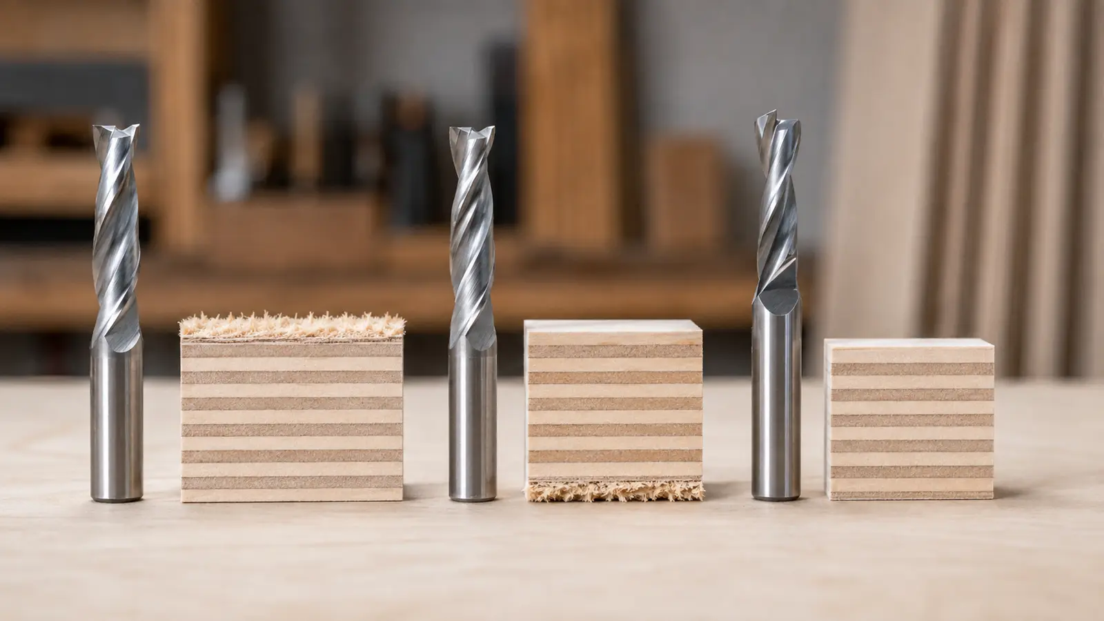
Viewed in a normal top-down routing setup, an upcut spiral pulls chips toward the collet and extraction area. The same lifting action can pull the top fibres away from the panel. A downcut spiral pushes chips toward the work and applies force into the top surface, which often reduces splintering there, but the chips need somewhere to go.
A compression cutter combines an upcut section near the tip with a downcut section closer to the shank. During a correctly positioned through-cut, the lower cutting edges draw the bottom veneer upward while the upper edges press the top veneer downward. Both forces point toward the core of the panel.
The labels describe flute action, not the machine’s commanded direction. Climb versus conventional cutting is a separate toolpath decision and does not turn an upcut bit into a downcut bit.
When an upcut bit is the better starting point
Upcut geometry is usually the practical first choice when the cut is deep, enclosed or likely to produce a large volume of chips. It helps move material out of a slot instead of forcing it beneath the cutter. That can reduce chip recutting and heat when extraction, feed and spindle speed are also appropriate.
Good candidates for upcut geometry
- deep grooves, mortises and closed pockets;
- roughing operations where evacuation matters more than the top edge;
- through-cuts where the upper surface will be hidden, refinished or trimmed later;
- cuts made from the back of a workpiece so the visually important face is supported on the opposite side.
What to watch
Top-edge fuzz, lifted veneer or small chips around the entry side indicate that the upward force is damaging the visible face. A sacrificial layer, a reversed workpiece orientation, a finishing pass or another geometry may help, but a dull edge and excessive runout must be ruled out first.
When a downcut bit is the better starting point
Downcut geometry is useful when the face under the router is the one that must remain clean. It is frequently chosen for shallow dadoes, surface pockets, lettering and laminated top faces because its cutting action presses toward the workpiece.
Good candidates for downcut geometry
- shallow grooves and rabbets with a visible top surface;
- surface work in veneer or laminate where top-edge breakout is unacceptable;
- operations where the bottom face is hidden or supported by a spoilboard;
- finishing passes that remove a small, controlled amount of material.
What to watch
Do not assume a downcut is automatically safe for a deep slot. Chips can be forced into the bottom of the cut, where they are recut and heated. Stop if the slot fills, the sound changes, the cut darkens or chips become powdery. Reduce the depth strategy, clear the slot, improve extraction or choose a geometry designed for the operation.
When a compression bit is the better starting point
Compression geometry is designed for panels whose top and bottom faces both need protection. It is especially relevant to through-cut profiles in double-sided veneer, melamine and other laminated sheet goods. It is not automatically the best bit for every plywood operation.
The transition position is the deciding detail
The short upcut section at the tip must remain below the top face during the finished cut. If that section reaches the top veneer, it can lift the very surface the compression geometry is supposed to protect. Compare the manufacturer’s upcut length with material thickness, first-pass depth, spoilboard penetration and remaining onion skin before programming the cut.
A standard compression bit may not deliver its intended top-face action during very shallow first passes. For staged cutting, manufacturers offer different transition lengths, including short-upcut or “mortise compression” designs. Select one from its drawing and application data; do not infer the transition from a product photo.
Entry and full-depth caution
Some compression cutters are intended to ramp or enter through a predrilled path rather than plunge vertically. A full-depth pass is appropriate only when the tool, machine rigidity, workholding, material and manufacturer data all support it. Never force a full-depth strategy merely to engage the compression zone.
Choose the geometry by operation
| Operation | Useful starting geometry | Why | Check before cutting |
|---|---|---|---|
| Deep pocket or closed mortise | Upcut | Prioritizes chip evacuation | Bottom finish, extraction and maximum depth per pass |
| Shallow dado with a visible top face | Downcut | Presses the top fibres toward the panel | Chip clearance and heat in the groove |
| Through-profile with both faces visible | Compression | Opposing flute sections support both faces | Transition length, lead-in and spoilboard penetration |
| Through-profile with the top face hidden | Upcut | Efficient evacuation may outweigh top-edge appearance | Bottom support and final breakout |
| Surface lettering or a shallow pocket | Downcut or application-specific cutter | Top-surface finish is usually the priority | Minimum detail size and chip clearing |
| Finishing an existing edge | Upcut, downcut or compression according to visible faces | The stock allowance is small and face priority decides | Feed direction, bearing or guide, and cutter engagement |
Routing plywood specifically? Use the material-focused guide Which Router Bit for Plywood? For a wider overview of profiles beyond spiral direction, see Types of Router Bits for Wood.
Dimensions, machine and setup
Shank and collet
Match the stated shank diameter to a clean, undamaged collet. Insert the shank deeply enough for secure grip while keeping the flute and radius clear of the collet. Do not bottom the bit against the inside of the collet, and do not clamp on the cutting flutes.
Cutting length and stickout
The cutting edge must cover the programmed engagement without substituting excessive stickout for the correct length. More projection increases leverage and deflection. Use the shortest suitable tool and confirm that the cutting length—not the overall length—matches the operation.
CNC, handheld and router table
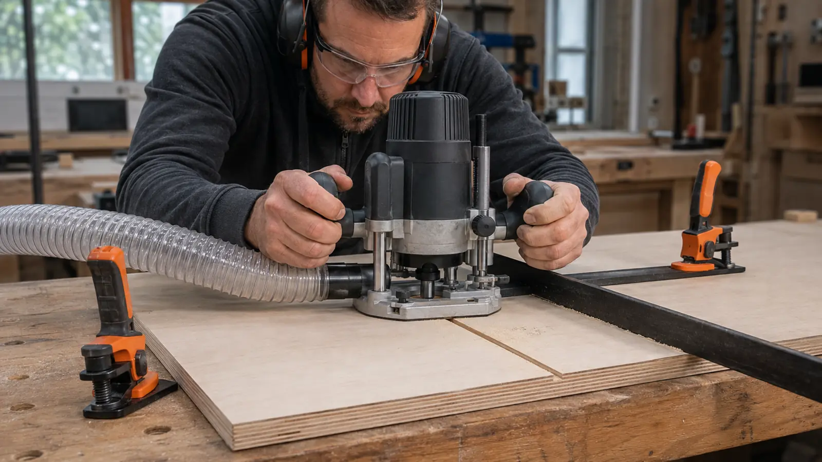
A CNC can control ramping, pass depth and transition placement consistently, but it still requires sound workholding and extraction. With a handheld router, guide the base securely, keep the work clamped and choose a manufacturer-approved bit for handheld use. On a router table, use guards and a controlled feed path; the physical “top” and “bottom” faces relative to the cutter may differ from a top-down CNC setup, so identify the visible face before choosing.
Material and manufacturer data
Plywood, MDF, solid wood, melamine and plastics do not produce the same chip or impose the same edge loads. Use the exact tool manufacturer’s application and cutting-data tables for the material, diameter and flute count. Generic RPM or feed figures copied from another cutter are not a safe specification.
Troubleshooting by symptom
| Symptom | Possible causes | Checks |
|---|---|---|
| Torn or fuzzy top edge | Upcut action at the surface, dull edge, runout or weak veneer | Inspect the bit and collet; test a downcut or correctly engaged compression geometry |
| Breakout at the bottom | Downcut action at the lower face, poor support or an uncontrolled final exit | Use a spoilboard, review final-pass strategy or test upcut/compression geometry |
| Dark groove, burning smell or hot bit | Packed chips, recutting, dull tool or unsuitable feed-to-speed relationship | Stop; clear chips, inspect sharpness and use the manufacturer’s cutting data |
| Compression bit still chips the top | Upcut section reaches the top face or the first pass is too shallow | Measure the transition and compare it with actual cutting depth |
| Chatter or wavy edge | Excessive stickout, weak workholding, runout or aggressive engagement | Shorten projection, secure the work and inspect spindle/collet condition |
| Powder instead of defined chips | Rubbing, dull edge or unsuitable cutting parameters | Stop and compare against the tool maker’s starting recommendations |
A conservative selection and test method
- Name the operation: through-cut, groove, pocket, trim or finishing pass.
- Mark the visible face: top, bottom or both.
- Estimate chip volume: deep closed cuts place more demand on evacuation.
- Read the tool drawing: confirm shank, diameter, cutting length, transition and approved machines.
- Use manufacturer starting data: stay below the stated maximum RPM and respect the recommended material range.
- Secure the setup: clamp the work, preserve guarding, connect extraction and keep the cutting path clear.
- Test on matching scrap: use the same material, support and orientation as the final part.
- Change one variable at a time: record sound, chips, edge quality and heat before the next adjustment.
Safety note: disconnect power before changing or inspecting a cutter. Keep guards in place, use eye and hearing protection, control wood dust and keep hands away from the cutting path. Stop immediately for smoke, unexpected vibration, a loose workpiece or a damaged tool.
Frequently asked questions
Is a compression bit always the cleanest choice?
No. Compression is most useful when both faces of a through-cut panel are visible and the transition is correctly positioned. For a deep pocket, an upcut may evacuate chips more effectively; for a shallow top-face groove, a downcut may be simpler and more appropriate.
Can I use a downcut bit for a deep dado?
Only when the specific cutter, pass strategy and chip-clearing method support it. Downcut action can pack chips in a closed slot. If chips accumulate or heat rises, stop and change the strategy rather than forcing the cut.
Why does my compression bit chip the top on the first pass?
The first pass may be shallower than the upcut section at the tip. In that case, upcut edges are still acting at the top surface. Review the transition length or use an application-specific short-upcut compression design.
Can these spiral bits be used in a handheld router?
Some can, but approval depends on the exact product. Check the manufacturer’s listed machines, maximum speed and feed guidance. Workholding, a stable guide, guarding and dust extraction remain essential.
Which geometry should I use for plywood?
It depends on whether the cut is a groove, pocket or through-profile and which veneer faces are visible. The dedicated plywood router-bit guide applies the geometry choice to those cases.
Technical references
- Freud Tools — Up Spiral Bit: manufacturer description of upward chip removal and compatible router types.
- Freud Tools — Down Spiral Bit: manufacturer guidance for grooves and dadoes in single-sided veneers and laminates.
- Freud Tools — Compression Spiral Bit: opposing cutting action for double-sided veneered or laminated materials.
- LMT Onsrud — Cutting Data Recommendations: material-specific starting data for routing products.
- Amana Tool — Maximum RPM Guide: reminder not to exceed the rating for the selected cutter.
- OSHA — Handheld Routers: workholding, guards, flying-chip and dust-control precautions.
The stated parameters are starting points. Test progressively on scrap and always respect manufacturer limits.