
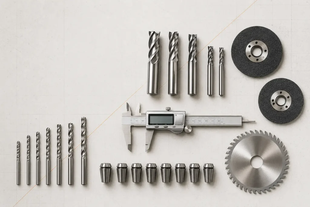
Speeds and feeds are not two independent numbers. They describe a cutting system that includes the exact tool, material, flute count, depth, radial engagement, machine, workholding, extraction and toolpath. A reliable starting point comes from the tool manufacturer, then a controlled test confirms whether the complete setup can produce a stable chip.
Quick answer: identify the exact cutter and approved material first. Take the manufacturer’s chip-load or feed guidance, calculate a compatible feed and RPM, check every machine limit, reduce engagement rather than arbitrarily slowing the feed, and test on matching scrap. Record one change at a time. Stop for smoke, chatter, loosening, abnormal heat or an unstable part.
What to know before calculating
Begin with the manufacturer’s document for the exact part number. A family name such as “6 mm two-flute spiral” is not enough: carbide grade, edge geometry, coating, flute volume, cutting length and intended machine can change the permitted range. Confirm that the reference is approved for the material and operation before copying any number.
Separate a limit from a target. Maximum RPM is a ceiling, not an instruction to run at that speed. A published chip-load range is generally tied to particular materials, diameters, tool families and engagement assumptions. Values from a similar-looking bit, a social post or a generic chart do not override the exact manufacturer’s data.
A conservative setup is not simply a very slow feed. Feeding too slowly can reduce chip thickness until the edge rubs and heats the material. A safer first test usually limits depth, width, tool projection and toolpath complexity while keeping feed and RPM inside the approved relationship.
Chip-load, feed and RPM formulas
For a basic rotating cutter, nominal chip load is the distance advanced per cutting edge during one spindle revolution. Manufacturer cutting-data sheets commonly use these relationships:
Chip load = feed rate ÷ (RPM × number of cutting edges)
Feed rate = RPM × number of cutting edges × chip load
RPM = feed rate ÷ (number of cutting edges × chip load)
Keep the units consistent. Feed in millimetres per minute produces chip load in millimetres per tooth; feed in inches per minute produces inches per tooth. Do not insert an inch value into a metric calculation. Count effective cutting edges as specified by the manufacturer: some specialty tools are not calculated merely by counting visible flutes.
The formula verifies a relationship; it does not determine whether the tool, machine, depth or material is compatible. It also describes a nominal straight-line value. Acceleration, cornering, runout and chip recutting can make the real cut behave differently.
Input checklist
| Input | What to record | Why it matters |
|---|---|---|
| Exact cutter | Brand, part number, diameter, shank, cutting length, flute count and geometry | Defines the applicable manufacturer data and physical limits |
| Material | Species or panel type, grade, coating, thickness and condition | Chip formation and abrasiveness vary substantially |
| Operation | Open profile, full-width slot, pocket, drilling, finishing or engraving | Chip evacuation and engagement are not equivalent |
| Engagement | Axial depth, radial width, stock allowance and number of passes | Changes load, heat, deflection and available flute space |
| Machine | Spindle range, power, maximum feed, acceleration, collet and rigidity | The controller may not achieve the requested motion safely |
| Setup | Stickout, runout, workholding, spoilboard, guarding and extraction | A sound calculation cannot compensate for unstable mechanics |
Worked example: calculation, not a recommendation
Assume the manufacturer of one exact two-edge cutter specifies a starting chip load of 0.10 mm per tooth for the selected material and engagement, and the verified spindle setting is 18,000 RPM. The nominal feed calculation is:
18,000 RPM × 2 edges × 0.10 mm/tooth = 3,600 mm/min
This result is valid only for the stated hypothetical inputs. It is not a universal recommendation for a 6 mm bit, plywood or any other category. Before using it, confirm that the machine can achieve the feed, the tool allows the RPM, the depth assumptions match and the workholding can resist the cutting force.
If the machine cannot reach a calculated feed, do not simply keep the same RPM and accept a much smaller chip. Return to the manufacturer’s permitted range and choose a compatible combination, tool or engagement. A single-edge cutter may sometimes suit a feed-limited machine better, but only when the exact product is approved for the task.
Depth and radial engagement change the answer
A full-width slot usually loads a cutter more heavily and traps chips more readily than a light profile. Increasing axial depth raises contact length and may require reduced chip load or another pass strategy according to the manufacturer. Some LMT Onsrud wood data sheets, for example, publish explicit reductions as depth rises; those reductions belong to the listed series and must not be copied blindly to every bit.
Check cutting length and flute capacity as well as depth. A long cutting edge does not automatically authorize a deep single pass. Excessive stickout increases leverage and deflection. For compression tooling, the transition must also be positioned correctly in the material. For downcut tools, chip packing can become the limiting factor even when the calculated chip load looks acceptable.
Finishing passes need planned stock. A near-zero-stock pass can rub instead of forming a stable chip. Use the tool maker’s finishing guidance and avoid repeated spring passes unless the process specifically requires them.
Programmed values versus real machine motion
A controller may display the requested feed while the machine moves more slowly through tight arcs, short segments or changes of direction. Acceleration limits, feed overrides, look-ahead, toolpath smoothing and a weak or overloaded spindle all affect the real cut. This explains why a straight section can be clean while corners burn.
Confirm the units used by the CAM file and controller. A metric/imperial mismatch can multiply or divide feed dramatically. Check the active override before every test, and verify that the post-processor has not inserted a plunge feed where a cutting feed was expected. The spindle may also lose speed under load, so sound alone is not a reliable tachometer.
Mechanical condition remains part of speeds and feeds. Clean the collet and shank, use the exact shank size, control projection, measure runout when appropriate and replace damaged components. One flute carrying most of the load invalidates the assumption that edges share the cut equally.
How to read the cut
Observe several signals together. Defined chips, stable sound, a secure part and no abnormal heat are more useful than one surface mark alone. Different materials form different chips, so compare the result with manufacturer examples and a known-good setup.
- Fine powder, dark edges or a rising smell: possible rubbing, dull tool, low nominal chip load, recutting or poor evacuation.
- Heavy chatter or periodic marks: possible excessive load, runout, deflection, weak workholding or unstable toolpath.
- Chips packed in the slot: geometry, extraction, flute space, depth or path may not evacuate the material.
- Top or bottom breakout: investigate geometry, entry, support and visible-face priority rather than changing feed alone.
- Plastic melting or rewelding: stop and review heat input, chip formation, polished geometry and evacuation using plastic-specific data.
Use the CNC wood-burning diagnostic when heat marks appear. For spiral direction and veneer protection, see Upcut vs Downcut vs Compression Router Bits.
A conservative, traceable test method
- Record the source: save the exact manufacturer document, product revision and access date.
- Verify the setup: tool, collet, runout, projection, workholding, guards and extraction come before parameter tuning.
- Calculate one baseline: keep units consistent and stay within every published and machine limit.
- Reduce risk through engagement: simplify the path and use an approved shallow or reduced-width test instead of an arbitrarily slow feed.
- Use matching scrap: same material, thickness, orientation and support as the final work.
- Change one factor: record feed, RPM, depth, width, toolpath, chips, sound and finish after each test.
- Test the difficult motion: include entries and corners; a long straight line does not validate the entire program.
- Stop on instability: smoke, chatter, loosening, abnormal heat, spindle distress or movement of the part ends the test.
The CNC and router-bit calculators can perform the arithmetic, but the manufacturer’s input remains essential. The tool selector can help identify a suitable tool family before calculation.
Troubleshooting table
| Observed result | Check first | Do not assume |
|---|---|---|
| Burning or very fine dust | Tool condition, actual feed, RPM relationship and chip evacuation | That lowering feed is safer |
| Chatter or tool deflection | Engagement, stickout, runout, rigidity and workholding | That RPM alone is responsible |
| Clean straights, burned corners | Acceleration, corner speed, dwell and toolpath segmentation | That the programmed feed is maintained everywhere |
| Good edge, unstable part | Cutting force, hold-down, tabs, vacuum and direction of cut | That finish proves the setup is safe |
| Chips recut in a deep slot | Flute direction, extraction, pass depth and flute capacity | That more RPM improves evacuation |
Safety
Manufacturer limits, machine instructions and guarding requirements take priority over any calculator. Isolate power before touching the cutter or collet. Secure the work, keep guards in place, use suitable eye and hearing protection and provide effective chip or dust extraction. Fine wood dust is a health and combustible-dust hazard; do not use compressed air to create a dust cloud.
A calculation does not authorize a tool for a machine. Handheld routers, CNC routers and router tables have different control, feeding and guarding requirements. Do not apply a CNC feed table to a handheld operation unless the exact manufacturer explicitly supports that use.
Frequently asked questions
What is the safest beginner feed rate?
There is no universal safe feed rate. Use the exact tool manufacturer’s data for the material and engagement, then verify machine limits and test on matching scrap. Reduce engagement rather than assuming an extremely slow feed is safer.
Is maximum RPM the recommended RPM?
No. Maximum RPM is a ceiling. The working value must also be compatible with feed, chip load, tool diameter, material, engagement, balance, spindle and manufacturer instructions.
Can I copy settings for another bit of the same diameter?
Not safely without verification. Flute count, geometry, carbide, coating, cutting length and intended material can differ even when diameter matches. Check the exact part number.
Should I lower the feed for a cautious first cut?
Not automatically. Too little feed can cause rubbing. Keep the manufacturer-approved feed/RPM relationship and lower risk by reducing approved engagement, simplifying the path and testing on scrap.
Why is the cut good on straight lines but burned in corners?
The machine may slow in corners because of acceleration, radius or toolpath segmentation while RPM remains constant. Review real motion, not only the programmed straight-line feed.
Technical references
- LMT Onsrud — Cutting Data Recommendations: manufacturer sheets by tool family and material.
- LMT Onsrud — MDF Cutting Data Recommendations: published chip-load, feed and RPM formulas with series-specific data.
- Amana Tool — Vectric Tool Library: manufacturer reminder that tool-database parameters are starting points to adjust for the project and material.
- Freud Tools — 52-524 cutter data: a product-specific example connecting chip load, feed, RPM and heat.
- OSHA — Woodworking routers: workholding and router operating hazards.
- OSHA — Wood dust: exposure and local-extraction guidance.
Important: this guide explains a verification method. It does not replace the cutting data, maximum ratings, machine manual or safety instructions for the exact tool and setup.
The stated parameters are starting points. Test progressively on scrap and always respect manufacturer limits.