
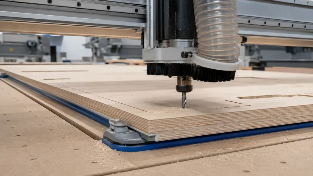
Burn marks are evidence that heat is building faster than the cut can remove it. On a CNC router, that heat usually comes from rubbing, recutting trapped chips, a dull or contaminated edge, excessive tool engagement, runout, or a toolpath that slows and dwells in one area. The dark edge is a symptom; the useful diagnosis is to identify why the cutter stopped making a healthy chip.
Quick answer: stop the machine, inspect the cutter and collet, clear the cut and compare the exact tool with its manufacturer data. If the tool and setup are sound, review feed, RPM, flute count, depth and toolpath as one system. Change only one factor at a time on matching scrap. Do not keep cutting through smoke or an increasing burning smell.
Why a CNC router burns wood
A sharp router bit removes defined chips. Those chips carry part of the cutting heat away from the edge. When each cutting edge removes too little material, it spends more time sliding across the surface. Friction rises, the wood darkens and resin can bake onto the cutter. A tool can also burn while apparently moving quickly if the pass is too deep, the slot is packed, the edge is dull or the machine loses feed in a corner.
Burning is therefore not proof that RPM alone is too high. Feed, spindle speed, flute count, diameter, cutting depth, radial engagement, geometry, sharpness, material and machine behaviour interact. Reducing RPM without checking the tool’s approved range or increasing feed beyond what the cutter and machine can support can create a different hazard. Start from the manufacturer’s data for the exact reference.
Common causes and first checks
| Possible cause | Why heat increases | First check |
|---|---|---|
| Feed too low for the selected RPM | Each edge removes a very thin chip and rubs the surface | Compare actual feed, RPM and flute count with the tool maker’s starting data |
| Dull, chipped or resin-coated cutter | The edge needs more force and no longer shears cleanly | Disconnect power, remove the tool and inspect it under good light |
| Chips trapped or recut | Hot particles remain in contact with the edge and workpiece | Inspect the slot, extraction path and flute direction |
| Pass too deep or engagement too high | The cutting load, deflection and contact area become excessive | Check the manufacturer’s depth guidance and the programmed engagement |
| Too many flutes for the available feed | Chip load per tooth becomes too small and flute space may be reduced | Confirm flute count and whether the machine can reach the required feed safely |
| Runout, damaged collet or excessive stickout | Edges do not share the load evenly and rubbing increases | Clean and inspect the collet, shank and spindle; measure runout when equipped to do so |
| Dwell, slow corner or repeated finishing passes | The edge remains in one location without enough fresh material to form a chip | Review lead-ins, corner speed, acceleration and duplicated toolpaths |
Feed, RPM and chip load
Chip load describes the nominal thickness removed by one cutting edge during one revolution. For a simple starting calculation:
Chip load = feed rate ÷ (RPM × number of cutting edges)
This formula organizes the relationship; it does not determine a safe value. Use the range published for the exact cutter, material and operation.
If RPM remains constant while feed is reduced, nominal chip load falls. If feed remains constant while flute count rises, the load per edge also falls. In both cases the cutter may rub rather than make a defined chip. Conversely, increasing feed indiscriminately can overload the tool, workholding or machine. A useful correction remains inside the cutter’s allowed speed, chip-load and engagement limits.
Verify commanded values against actual machine behaviour. Feed overrides, acceleration limits, small arcs, controller look-ahead and toolpath segmentation can make the real feed near a corner much lower than the programmed straight-line value. That is why a straight edge may look acceptable while corners are black.
Tool, collet and spindle condition
Do not tune software around a damaged cutting system. Isolate power before touching the cutter. Check for a chipped edge, rounded cutting line, discoloration, resin or pitch, a scratched shank and evidence that the collet has clamped on a flute. Clean only by a method approved for the tool and replace a damaged cutter; sharpening must preserve the intended geometry.
Inspect the collet and nut for dirt, corrosion, cracks and wear. Match the shank diameter exactly, keep the cutting flutes outside the collet and avoid bottoming the shank in the holder. Excessive projection increases leverage and vibration. Runout can make one flute carry most of the cut while another rubs, producing heat even when the programmed values appear reasonable.
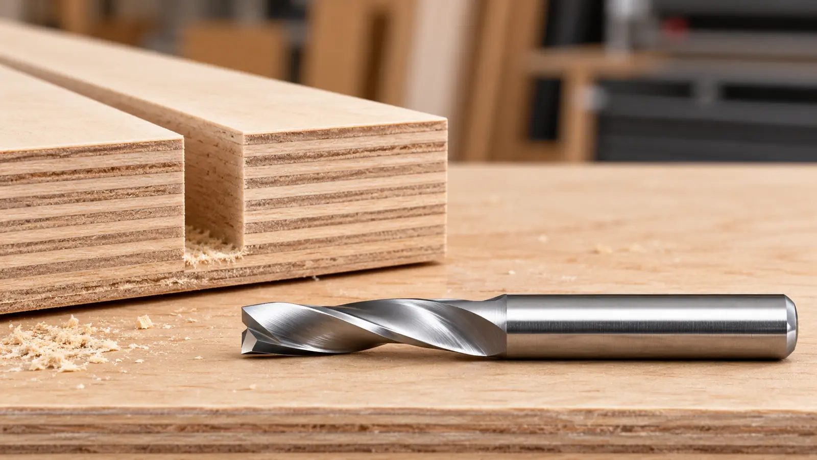
A photograph cannot prove that an edge is sharp or that runout is acceptable. Use a physical inspection and, where appropriate, a suitable measuring method. If a cleaned, correctly mounted cutter still produces fine powder, rising noise or heat, stop and compare it with a known-good tool rather than compensating indefinitely in the program.
Chip evacuation and depth of cut
Chips should leave the cutting zone instead of circulating in the slot. A deep closed groove makes evacuation harder than an open profile. Downcut geometry can protect the top face but pushes chips into the cut; upcut geometry usually assists evacuation but may affect the top edge. Compression geometry has its own transition and engagement requirements. Choose geometry from the operation, material and visible faces, not from the word “wood” alone.
Inspect whether the brush shoe, hose and airflow actually capture chips at the cutter. A connected hose is not proof of effective extraction. Check for blockage, leakage, a brush that seals too tightly or sits too high, and a slot that closes around the cutter. Never use an improvised airflow method that spreads fine combustible dust through the workshop.
Depth and width of cut change the load. When the tool is buried deeply or slots at full diameter, it has more contact and less room to shed chips. Use the depth recommendations for the exact tool series. If the manufacturer requires lower chip load or reduced engagement at greater depth, follow that guidance. Several controlled passes may be safer than forcing one deep pass, but very shallow repeated passes can also rub if the toolpath and parameters are unsuitable.
Corners, plunges and toolpath behaviour
Burning at one location often points to motion rather than a global feed-and-speed error. Common examples include a dwell at the start, a vertical plunge with a cutter not approved for it, a tight internal corner where the controller reduces feed, or a lead-out that pauses before retracting. Inspect the toolpath simulation and the machine’s real motion.
- Use an entry method approved for the cutter, such as a ramp or helical entry when specified.
- Avoid unnecessary pauses while the spindle remains in contact with the wood.
- Review acceleration and cornering behaviour instead of judging only the programmed feed.
- Do not repeat zero-stock finishing passes unless the tool maker and process support them.
- Confirm that tabs, onion skins and final passes do not leave the cutter rubbing against a flexible part.
Diagnose the visible symptom
| Symptom | Likely direction | What to verify |
|---|---|---|
| Dark marks along the entire edge | Rubbing, dull edge, unsuitable feed-to-RPM relationship or excessive engagement | Tool condition, manufacturer data, actual feed and pass strategy |
| Burning mainly in corners | Machine slows, dwells or recuts in small radii | Corner speed, acceleration, tool diameter and toolpath smoothing |
| Burn at plunge or entry point | Unsuitable entry or stationary contact | Plunge capability, ramp settings and lead-in |
| One side burns more than the other | Runout, deflection, grain direction or uneven chip removal | Collet, stickout, spindle condition, climb/conventional direction and workholding |
| Fine powder, high-pitched sound and hot cutter | Rubbing or dull cutting edge | Stop immediately; inspect the tool and compare chip load with manufacturer data |
| Smoke or glowing dust | Immediate fire risk | Stop safely, isolate the machine and follow the workshop emergency procedure |
A conservative correction method
- Stop and preserve evidence: note where the mark starts, the material, tool reference, RPM, feed, depth, flute count and toolpath.
- Inspect mechanically: check the cutter, collet, projection, runout, workholding and extraction before changing parameters.
- Open the exact manufacturer data: confirm approved materials, machines, RPM ceiling, chip-load range and engagement limits.
- Reproduce on matching scrap: use the same material, orientation, support and extraction.
- Change one variable: adjust only within the published range and record the result.
- Observe chips, not colour alone: look for defined chips, stable sound, clean edges and no abnormal heat.
- Validate corners and entries: a straight test line does not prove the complete toolpath is sound.
- Reject an unstable result: smoke, loosening, chatter, increasing temperature or an unusual sound requires another stop and inspection.
For a systematic starting-point calculation, use the CNC and router-bit calculators only with the exact manufacturer’s values. For flute-direction effects, see Upcut vs Downcut vs Compression Router Bits. If the material is plywood, continue with Which Router Bit for Plywood?
Dust, smoke and fire safety
Smoke is not a normal tuning signal. Stop the cut, use the machine’s safe stop procedure and isolate energy before inspection. Do not touch a hot cutter. Smouldering wood dust can remain hidden in a spoilboard, hose, shoe or extraction system. Follow the machine, extraction and workshop emergency instructions, and keep the appropriate fire controls available and maintained.
Fine wood dust is both a health hazard and a combustible material. Use effective local extraction, suitable respiratory protection where required, eye and hearing protection, sound guarding and good housekeeping. Do not blow accumulated fine dust into the room. Any persistent burning, arcing, abnormal bearing heat or electrical smell requires qualified inspection rather than a feed-and-speed adjustment.
Frequently asked questions
Should I reduce RPM when the wood burns?
Not automatically. Burning indicates excessive heat, but the cause may be low feed, a dull cutter, trapped chips, runout, deep engagement or a slowing toolpath. Compare feed and RPM together with the manufacturer’s data before changing either value.
Should I increase the feed rate?
Only when the tool, machine, workholding and published cutting range support it. An increase may reduce rubbing when chip load is too small, but an arbitrary increase can overload the cutter or move the part.
Why does the CNC burn only in corners?
The controller may reduce actual feed in a tight radius while spindle speed remains constant. A dwell, small segmented moves, an unsuitable cutter diameter or repeated contact can also be responsible. Review real motion and the toolpath.
Can a dirty router bit cause burning?
Yes. Resin and pitch can increase friction and hide damage. Disconnect power, remove and inspect the cutter, and use only a cleaning method compatible with the tool. Replace damaged edges.
Is a burn mark only a cosmetic defect?
No. It can indicate rubbing, damaged tooling, poor evacuation or unstable cutting. Smoke and hot dust also create a safety concern. Stop and diagnose the cause before continuing.
Technical references
- Freud Tools — 52-524 T-slot cutter: manufacturer guidance explaining that an excessively small chip load can make the cutter rub and burn the material.
- Freud Tools — 12-130 double-flute router bit: product-specific starting guidance and a reminder to adjust feed when burning is observed.
- LMT Onsrud — Cutting Data Recommendations: material- and tool-family-specific routing data.
- OSHA — Woodworking fire and explosion hazards: fire risk associated with sawdust and fine wood dust.
- OSHA — Wood dust control: local exhaust guidance for woodworking machinery.
Important: this guide provides a diagnostic method, not cutting data for a specific product. The exact cutter manufacturer, machine manual and dust-extraction instructions remain authoritative.
The stated parameters are starting points. Test progressively on scrap and always respect manufacturer limits.